

Top
Authors
Published
24 Feb 2026Form Number
LP2372PDF size
53 pages, 8.3 MBSubscribed to LP2372.
Thank you for your feedback.
Table of Contents
Abstract
This paper outlines Lenovo’s optimized Reference Architectures for High Performance Computing (HPC) environments tailored to Computer Aided Engineering (CAE) workloads such as Computational Fluid Dynamics (CFD) and Finite Element Analysis (FEA). It explains how modern CAE simulations rely on high bandwidth, low latency fabrics—specifically the Cornelis CN5000 Omni Path—and how emerging memory technologies like MRDIMMs significantly accelerate performance. Benchmark results demonstrate substantial gains in scalability, throughput, and efficiency, particularly for demanding CFD workloads.
To support organizations of all sizes, the document presents modular reference architectures for Entry and Scale-Out HPC clusters, using Lenovo ThinkSystem servers with Intel or AMD CPUs, along with Lenovo Neptune direct water cooling for large scale deployments. These architectures deliver validated, repeatable building blocks that simplify cluster design, integration, and implementation through Lenovo EveryScale. The result is a set of end to end, production ready blueprints enabling customers for deploying CAE optimized HPC clusters that maximize performance, reliability, and total cost efficiency.
This paper is for technical compute architects and economic decision makers involved in CAE driven HPC purchases of infrastructure optimized for CFD.
Introduction
This paper provides Reference Architectures for High Performance Computing (HPC) systems, optimized for Computer-Aided Engineering (CAE) Computational Fluid Dynamics (CFD) and Finite Elements Analysis (FEA) workloads. These HPC systems use Lenovo ThinkSystem Servers, integrated with the latest generation Cornelis Networks CN5000 Omni-Path® high performance fabric switches and SuperNICs. With its high-bandwidth, low-latency characteristics, Omni-Path is an ideal technology for CAE workloads and perfectly matches the Lenovo ThinkSystem high-performance servers.
This document is structured as follows:
- This first section describes CAE and CFD / FEA workloads and how they can benefit from HPC technology: Cornelis CN5000 Omni-Path High Performance Fabric as well as MRDIMM CPU memory.
- The second section provides an overview of the CAE Reference Architectures for Entry Clusters. It includes a description foundational building blocks and how to scale them to different “T-shirt solution sizes”, interconnected with a Cornelis CN5000 Omni-Path Switch and Ethernet Management networks.
- The third and fourth sections describe the detailed configurations for the CAE Reference Architectures for Entry Clusters using Intel / AMD CPUs. They provide descriptions of the Lenovo air-cooled servers as well as a detailed Bill of Materials (BOM) of the components.
- The fifth section provides an overview on the CAE Reference Architectures for Scale-Out Clusters, which are then detailed in sections six and seven for Lenovo ThinkSystem direct-water-cooled servers with Intel and AMD CPUs. As for the Reference Architectures for Entry Clusters, the Lenovo servers are then described in more detail and Bills of Materials are provided.
- In the final section, a management summary is provided, followed by an Appendix including additional information.
Computer-Aided Engineering and HPC
In today’s marketplace, where innovation, speed, and precision define success, Computer-Aided Engineering (CAE) has become indispensable for modern product development. By simulating and analyzing the physical behavior of products and systems in a virtual environment - well before physical prototypes exist - CAE helps organizations cut development costs, accelerate time-to-market, and enhance product quality and performance.
This section provides an overview on Computer-Aided Engineering (CAE) workloads and how High Performance Computing (HPC) technologies together with Lenovo EveryScale enable an efficient and cost-optimized solution.
Topics in this section:
CAE and Lenovo Reference Architectures
From automotive and aerospace to energy, manufacturing, and consumer electronics, CAE empowers critical engineering decisions. It enables teams to explore design alternatives, validate performance under real-world conditions, and ensure compliance with safety and regulatory standards. As products grow more complex and expectations rise, the ability to virtually simulate and optimize designs has shifted from luxury to a competitive necessity.
Among the most powerful and widely adopted CAE technologies is Computational Fluid Dynamics (CFD). CFD enables the simulation of fluid behavior - both liquids and gases - as they interact with surfaces and environments. It is indispensable in industries such as aerospace, automotive, energy, and electronics, where mastering airflow, heat transfer, and fluid dynamics is critical to product success. For example, CFD empowers engineers in evaluating airflow around aircraft wings or vehicle bodies for minimizing drag and boosting fuel efficiency. Other applications of CFD are enhancing cooling systems in electronics and power equipment or improving the safety and performance of pumps, turbines, and other fluid-handling machinery.
Finite Element Analysis (FEA) is another application of Computer-Aided Engineering, used to simulate how products respond to real-world forces such as stress, vibration, heat, and other physical effects. By breaking down complex geometries into smaller, manageable elements, FEA enables engineers to predict performance, identify weaknesses, and optimize designs before building prototypes.
There are two primary approaches to FEA: implicit and explicit.
- Implicit FEA solves equations using iterative methods that assume equilibrium at each time step, making it well-suited for static or slowly changing problems such as structural loading or thermal analysis.
- Explicit FEA, on the other hand, calculates responses directly at very tiny time increments without assuming equilibrium, which makes it ideal for highly dynamic, nonlinear events like crash simulations, impact analysis, or explosions.
Together, these methods allow engineers to address a wide spectrum of design challenges, from long-term durability to short-duration, high-intensity events.
The following sub-sections provide an overview on various use cases for CFD applications, some popular applications and how CAE workloads and CFD applications benefit for High Performance Computing (HPC) technologies, specifically Cornelis CN5000 Omni-Path and MRDIMM Memory.
CFD use cases
CFD enables engineers to:
- Analyze airflow over aircraft wings or vehicle bodies to reduce drag and improve fuel efficiency.
- Optimize cooling systems in electronics and power equipment.
- Simulate ventilation and air quality in buildings and industrial facilities.
- Improve the performance and safety of pumps, turbines, and other fluid-handling equipment.
- Support city planning by modelling urban heat effects.
However, CFD simulations often involve solving millions of equations to capture the complex physics of fluid or air motion. CFD workloads are both compute-intensive and memory-intensive, requiring significant processing power and high memory bandwidth to solve complex physical models. These simulations typically scale efficiently across many CPU cores and nodes, making them ideal for High Performance Computing (HPC) clusters where the infrastructure enables large-scale execution - reducing turnaround time, improving model accuracy, and supporting more robust design optimization. The foundational technology for enabling efficient large-scale out across multiple Compute Nodes is a high-speed interconnect, as provided by the Cornelis CN5000 Omni-Path® High Performance Fabric. The ability to increase complexity of the model at scale allows more factors to be considered - including macro factors affecting designs.
CFD Software Platforms
Leading CFD Software Platforms are
- ANSYS® Fluent®
One of the most widely adopted CFD tools in the industry, Fluent® offers robust capabilities for simulating complex fluid flow, turbulence, heat transfer, and chemical reactions. It is used extensively in aerospace, automotive, energy, and electronics sectors for high-fidelity simulations and design optimization. - Siemens™ Simcenter™ STAR-CCM+™
STAR-CCM+™ is known for its integrated multiphysics capabilities, combining CFD with thermal, structural, and motion analysis. It is particularly valued for its automation, scalability, and ability to handle complex geometries and transient simulations, making it a strong choice for advanced engineering applications. - OpenFOAM®
An open-source CFD toolbox, OpenFOAM® is widely used in academia and industry for its flexibility and extensibility. It supports a wide range of solvers and physical models and is ideal for organizations looking to customize their simulation workflows or reduce licensing costs.
Most commercial CFD software from CAE ISVs is traditionally licensed based on the number of CPU cores used, which can constrain scalability and increase costs for large simulations. However, newer licensing models - such as STAR-CCM+’s Power Session and Fluent’s HPC Ultimate - remove core count restrictions, allowing users to fully leverage high-core-count systems without incurring additional licensing fees. These models, along with open-source solvers like OpenFOAM, are reshaping computing strategies by encouraging the use of high-density CPUs that prioritize total throughput over per-core efficiency. This shift opens new opportunities for maximizing simulation performance and return in investment modern CAE environments.
CAE workloads and how they benefit from HPC technology
Understanding the behavior of CAE workloads is important for creating an optimized High Performance Computing (HPC) cluster solution as the platform for running those workloads.
The following table provides an overview of the different characteristics of the CFD & Explicit FEA workloads compared to Implicit FEA workloads and the resulting requirements for HPC Compute Nodes:
In the following section, we describe how two High Performance Computing (HPC) technologies can positively impact CAE applications, especially in CFD:
- Cornelis CN5000 Omni-Path - a low-latency, high-bandwidth High Performance Fabric
- MRDIMM - a high-bandwidth memory technology
How CAE workloads benefit from Cornelis CN5000 Omni-Path Fabric
HPC workloads such as CAE/CFD depend on an interconnect network for running the simulations in parallel on and exchanging information between the Compute Nodes of the HPC solution. Key network features enabling rapid completion of CFD simulation are message rates, latency as well as network topology and flow optimization. As part of a Lenovo EveryScale solution, Cornelis CN5000 Omni-Path excels in providing superior message rates at ultra-low latency.
The following sub-sections explain the Cornelis CN5000 Omni-Path Fabric and it’s features, show the excellent scaling behavior of CAE workloads on an increasing number of Compute Nodes and conclude with a summary of the advantages of using this technology in the CAE context.
- Cornelis CN5000 Omni-Path Fabric
- Scaling of CFD applications on the CN5000 Omni-Path High Performance Fabric
- Conclusion
Cornelis CN5000 Omni-Path Fabric
The Cornelis CN5000 Omni-Path Fabric is ideal for interconnecting resources, using a scalable, high-speed, low-latency fabric, delivering an exceptional set of high-speed networking features and functions.
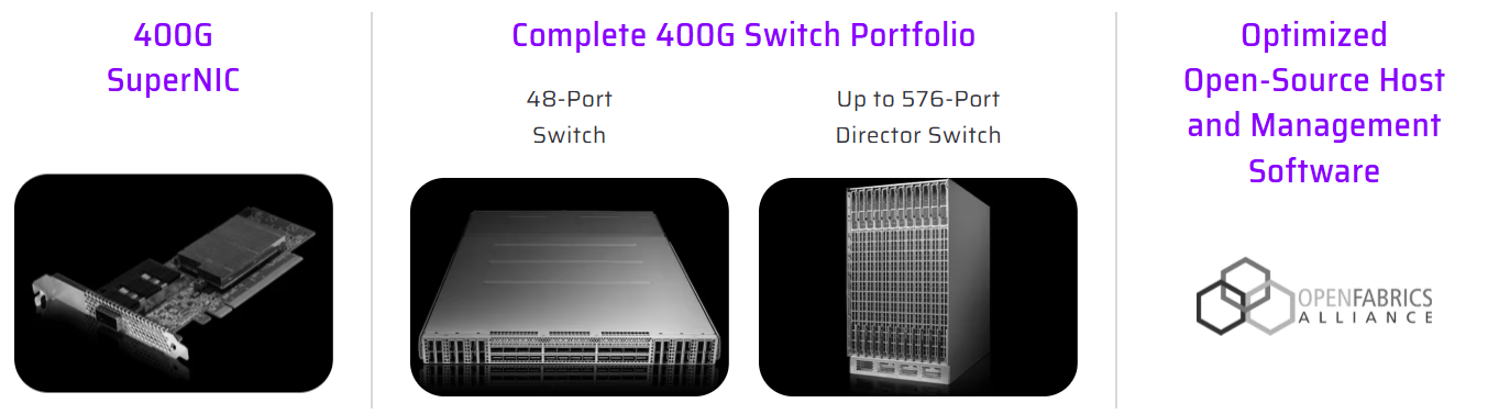
Figure 1. Cornelis Networks CN5000 Omni-Path
Cornelis Networks CN5000 Omni-Path is a complete, end-to-end 400Gb/s scale-out High Performance Fabric designed to accelerate tightly coupled HPC workloads such as CFD, from small departmental clusters to very large multi-rack systems. The solution spans the full fabric building blocks - PCIe Gen5 SuperNICs (single- and dual-port, air- or liquid-cooled), 48-port 1U switches, and a director-class 576-port switch platform for large, low-diameter topologies—plus qualified cabling options for dense deployment. Because CN5000 is delivered as an integrated “host-to-switch-to-fabric-management” stack, it is intended to provide predictable results and straightforward scaling as CFD problem sizes and node counts increase.
For CFD and other latency- and message-rate-sensitive MPI applications, CN5000 emphasizes lossless, congestion-free fabric behavior using credit-based flow control, advanced congestion management, and fine-grained adaptive routing guided by fabric telemetry - capabilities designed to preserve performance under real multi-job, high-utilization conditions. The SuperNIC is specified for up to 400Gb/s bandwidth with latency as low as <1µs, enabling strong halo-exchange and collective performance as solver partitions scale out. These architectural features translate into higher sustained application throughput (including reported CFD speedups versus alternative 400Gb/s fabrics), particularly as cluster size grows and communication overhead becomes dominant.
Ease of deployment and operational openness are addressed through the Cornelis OPX Software Suite, an open-source, OpenFabrics-based software stack that includes host drivers, fabric management, and monitoring/diagnostics, and is designed to integrate cleanly with common HPC environments. OPX provides Verbs compatibility and an OFI/libfabric path used broadly by modern MPI stacks and communication layers, helping CFD environments adopt CN5000 without requiring application rewrites.
Cornelis CN5000 is built on the Omni-Path Architecture to specifically optimize for HPC and AI performance. Key architectural pillars of Omni-Path include:
- Credit-Based Flow Control: Ensures packets are sent only when receive buffers have available credits, preventing overrun and eliminating pause frames. Credit-based flow control allows
per-virtual-lane flow regulation, enabling fair allocation across competing workloads. - Enhanced Congestion Avoidance: Uses forward and backward-propagating telemetry to dynamically adjust pacing at the source. This avoids the classic cascading congestion seen in oversubscribed topologies and maintains consistent throughput even under hot-spot pressure.
- Fine-Grained Adaptive Routing: Real-time telemetry builds a global heatmap of switch buffer utilization, enabling path selection based on current network state rather than static tables. It automatically bypasses congested paths, reducing long-tail latency and improving collective efficiency.
- Dynamic Lane Scaling and Link-Level Replay: Each link can degrade gracefully if individual lanes fail, maintaining connectivity instead of triggering a full path teardown. Link-level replay catches forward-error-correction (FEC) misses at the hardware layer, eliminating costly end-to-end retransmissions
- Open and Interoperable:Open software stack (OPX) built on OFI/libfabric, ensuring low-overhead integration with MPI stacks (for example, Open MPI), and ease of deployment in heterogeneous environments.
Scaling of CFD applications on the CN5000 Omni-Path High Performance Fabric
Maintaining performance on distributed infrastructure is critical for meeting the growing demands of complex CFD simulations. Strong scaling efficiency is the key metric, ensuring that investments in additional Compute Nodes translate directly into faster results rather than diminishing returns from network bottlenecks. CN5000 delivers exceptionally strong and consistent scaling across a number of ANSYS models, showing great efficiency from one to eight nodes.
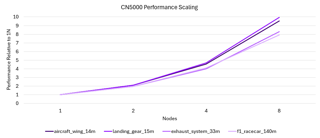
Figure 2. CN5000 Performance Scaling
This scaling behavior makes CN5000 Omni-Path an excellent High Performance Fabric technology for scaling-out CAE workloads to a larger number of nodes.
Conclusion
In summary, the CN5000 Omni-Path Fabric offers many advantages as part of Lenovo EveryScale CAE reference architectures:
- Enables faster simulation runtimes on CFD workloads, resulting in more simulations completed in the same time frame.
- Provides excellent scaling efficiency across nodes, which keeps performance growing closer to linearly as more servers are added, which is critical for large models.
- Sustains a high MPI message rate, which benefits CAE solvers that exchange many small messages between nodes. This improves the solver’s ability to keep all CPUs busy.
- Reduces end-to-end latency, helping to reduce idle wait times between Compute Nodes, which is an important factor for tightly coupled solvers in CFD and similar CAE tasks.
How CAE workloads benefit from MRDIMM technology
The following sub-sections explain the difference of memory-bound versus compute-bound CFD workloads, the specifics of MRDIMM in contrast to standard Memory technology, the impact on CFD applications measured in the Lenovo labs and conclusions.
- Memory-bound vs. compute-bound CFD workloads
- MRDIMM technology introduction
- Methodology and results
- Conclusion
Memory-bound vs. compute-bound CFD workloads
The performance characteristics of CAE and especially CFD workloads are typically balanced between compute-intensive and memory-intensive demands. Compute-intensive workloads benefit from a high number of processor cores, elevated CPU frequencies, and increased instructions per cycle (IPC), which accelerate the execution of scalar and vector operations. In contrast, memory-intensive workloads depend heavily on high memory bandwidth and low latency, as performance is closely tied to the speed at which data can be read from and written to memory. Additionally, larger CPU caches can help mitigate memory bottlenecks by reducing the frequency of main memory accesses.
The degree to which a CFD workload leans toward compute or memory intensity depends on several factors, including the specific software application, the resolution of the simulation model, and the complexity of the physics being modeled. Higher-resolution models—which involve finer meshes and more detailed physics—tend to be more memory-bound, requiring greater memory bandwidth to maintain simulation efficiency. Conversely, lower-resolution models and simulations with chemical reactions such as combustion models are often more compute-bound and benefit from CPUs with higher clock speeds and strong single-threaded performance.
MRDIMM technology introduction
MRDIMM technology, or multiplexed rank DIMMs, represents a significant advancement in memory performance, particularly for memory-intensive workloads such as CFD. Companies like Micron have been at the forefront of developing high-speed memory solutions, contributing to the reliability and efficiency of MRDIMMs.
The Lenovo ThinkSystem SC750 V4, as used in the Lenovo Reference Architecture for scale-out CAE using Intel-CPUs, is Lenovo’s first system to support this innovative technology and is one of the few systems in the market which can leverage the full potential of MRDIMM technology.
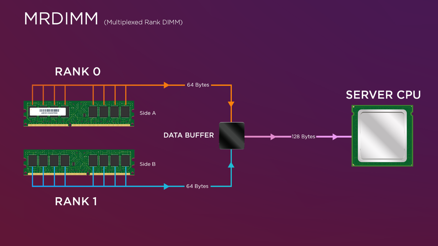
Figure 3. MRDIMM Multiplex Functionality
Operating at speeds of up to 8800 MT/s, MRDIMMs significantly reduce memory access latency and increase bandwidth, especially when paired with Intel Xeon 6th Gen processors. This combination has demonstrated up to a 200% performance improvement over the previous Xeon generation, making MRDIMMs a critical enabler for modern HPC environments. These benefits are particularly impactful for computationally intensive workloads like CFD, where memory speed and efficiency directly influence simulation performance. In real-world testing, CFD applications such as Fluent, STAR-CCM+, and OpenFOAM have shown an average of 1.2× faster computational times with MRDIMMs—highlighting the tangible value of high-bandwidth memory in accelerating engineering workflows.
Methodology and results
The following benchmark results highlight the performance impact of MRDIMMs across three leading CFD applications: ANSYS Fluent, Siemens Simcenter STAR-CCM+, and OpenFOAM. A diverse set of simulation models was selected, spanning from low-resolution models – such as Fluent’s Aircraft Wing model with 14 million cells (under 20 million cells) to high-resolution models exceeding 100 million cells, including STAR-CCM+’s VTM Bench model with 178 million cells. These benchmarks also included complex flow scenarios, such as thermal management simulations, to reflect real-world engineering challenges.
This range of model sizes and physics ensures a representative mix of workloads relevant to the broader engineering community. When averaged across all three applications and workload types, the Intel Xeon 6900-Series with MRDIMMs delivers a 2.4x overall performance improvement compared to the previous generation—highlighting its significant impact in accelerating CFD simulations across a broad range of use cases.
The chart below compares the performance of a 2-socket Compute Node featuring Intel 8592+ CPUs (Xeon 5) against a node equipped with Intel 6980P CPUs (Xeon 6) and MRDIMMs. It highlights relative performance across a range of Fluent, STAR-CCM+, and OpenFOAM workloads as model resolution increases. Performance is shown relative to the Intel 8592+ baseline, illustrating the gains achieved with the newer Xeon 6 architecture.
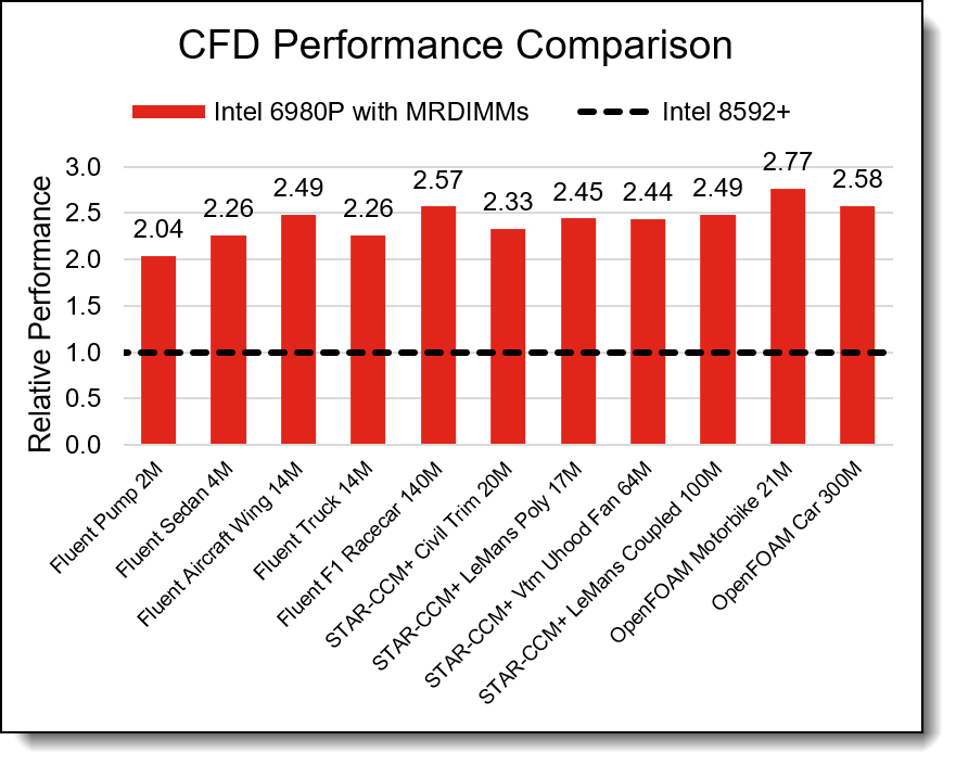
Figure 4. CFD Application Performance Comparison
Both memory bandwidth and compute power are key drivers of CFD workload performance. While it may be tempting to attribute the performance gains shown above solely to generational CPU improvements, further analysis reveals a more nuanced picture. When using the same Intel Xeon 6980P CPU configured with both MRDIMMs and standard DDR5 RDIMMs, the results indicate that the observed performance improvements are not solely due to CPU advancements. Servers with MRDIMMs deliver an additional performance improvement of 1.2× over DDR5 RDIMMs.
The chart below compares the performance of two 2-socket Compute Nodes, both featuring Intel 6980P CPUs, one configured with DDR5 RDIMMs and the other with MRDIMMs. It highlights relative performance across a range of Fluent, STAR-CCM+, and OpenFOAM workloads as model resolution increases. Performance is shown relative to the RDIMM-based node, illustrating the performance gains enabled by the MRDIMM memory technology.
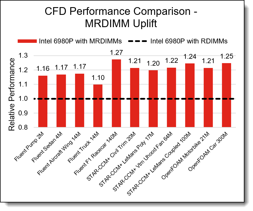
Figure 5.CFD Application MRDIMM Uplift
The results presented above are derived from benchmark runs by Lenovo HPC Innovation Center using the Lenovo ThinkSystem SC750 V4 with Intel Xeon 6 CPUs and Micron MRDIMM memory.
Conclusion
We found that Intel Xeon 6900-Series with MRDIMMs delivers a 2.4x overall performance improvement compared to the previous generation. Within that CPU generation, servers with MRDIMMs deliver an additional performance improvement of 1.2× over DDR5 RDIMMs.
Designing and delivering an HPC solution for CAE with Lenovo EveryScale
The increasing sophistication of the simulations - often involving millions of variables and intricate physical interactions - requires immense computational power. This is where High-Performance Computing (HPC) becomes a game-changer. HPC platforms deliver the speed and scale needed to run large, high-fidelity simulations efficiently. With HPC, engineering teams can evaluate more design options, build richer models, and make faster, data-driven decisions that drive innovation forward.
High Performance Computing uses Clusters of Servers, which are also known as Compute Nodes. The Compute Nodes are interconnected with a fast, high-bandwidth, low-latency network called the High Performance Fabric, and accessed and managed through servers known as Login and Management Nodes or Head Nodes as well as Ethernet Management Networks.
The design, manufacturing, integration, delivery and installation of such a HPC Cluster is a complex task, and Lenovo has extensive experience and knowledge of how to manage such a project with customers.
For the initial HPC cluster design phase, the Lenovo Reference Architectures as described in this document provide pre-defined and optimized Building Blocks (BBs) or Scalable Units (SUs) for CAE solutions. They were created by Lenovo Subject Matter Experts and Performance Engineers and deliver the compute power, memory bandwidth, and High Performance Fabric performance required to run CAE workloads efficiently and at scale. Application performance improvements and scalability have been validated by Lenovo’s expert performance engineers using production level hardware in the Lenovo HPC Innovation Center.
The Lenovo EveryScale solution is a way to simplify design, delivery, installation and implementation of HPC cluster solutions. Lenovo Server and Networking components and Operating System come together as a single Lenovo EveryScale Solution. Lenovo EveryScale provides Best Recipe guides to warrant interoperability of hardware, software and firmware among a variety of Lenovo and third-party components.
Addressing specific needs in the data center, while also optimizing the solution design for application performance, requires a significant level of effort and expertise. Customers need to choose the right hardware and software components, solve interoperability challenges across multiple vendors, and determine optimal firmware levels across the entire solution to ensure operational excellence, maximize performance, and drive best total cost of ownership.
Lenovo EveryScale reduces this burden on the customer by pre-testing and validating a large selection of Lenovo and third-party components, for creating a Best Recipe of components and firmware levels that work seamlessly together as a solution. From this testing, customers can be confident that such a best practice solution will run optimally for their workloads, tailored to the client’s needs.
In addition to interoperability testing, Lenovo EveryScale hardware is pre-integrated, pre-cabled, pre-loaded with the best recipe and optionally an OS-image and tested at the rack level in manufacturing, to ensure a reliable delivery and minimize installation time in the customer data center.
RA for Entry Clusters - Overview
The Reference Architecture (RA) for Entry Clusters is intended to provide people with limited experience in High Performance Computing (HPC) Clusters (e.g. customers moving their CAE workloads from dedicated Workstations to a shared Cluster solution) with a basic understanding of the various components and how they work together. The components, also referred to as Building Blocks (BBs), are based on Lenovo ThinkSystem air-cooled servers. They are interconnected with the Cornelis CN5000 Omni-Path High Performance Fabric as well as Ethernet Management networking.
The Reference Architecture provides configuration templates for Small (S), Medium (M), Large (L) and Extra-Large (X-L) Cluster sizes, based on common server and networking components. Those T-shirt sizes are intended as initial guidelines and can easily be adjusted to specific requirements by adding or removing components. They are provided for servers using Intel as well as AMD CPUs.
The target audience for this Reference Architectures are cost-sensitive environments with only a few dedicated and named users. They generally do not separate Login and Management systems but rather combine them in a single a Head Node serving both purposes. Security and access to the cluster is usually controlled externally (e.g. by using firewalls). If desired, additional Head Nodes allow us to separate User Login from Administrator Management, as outlined for the X-Large configurations.
A Storage Server with internal NVMe drives serving as NFS (Network File System) server is suggested for this Reference Architectures. Other shared storage options like parallel file systems can be considered for higher performance demands.
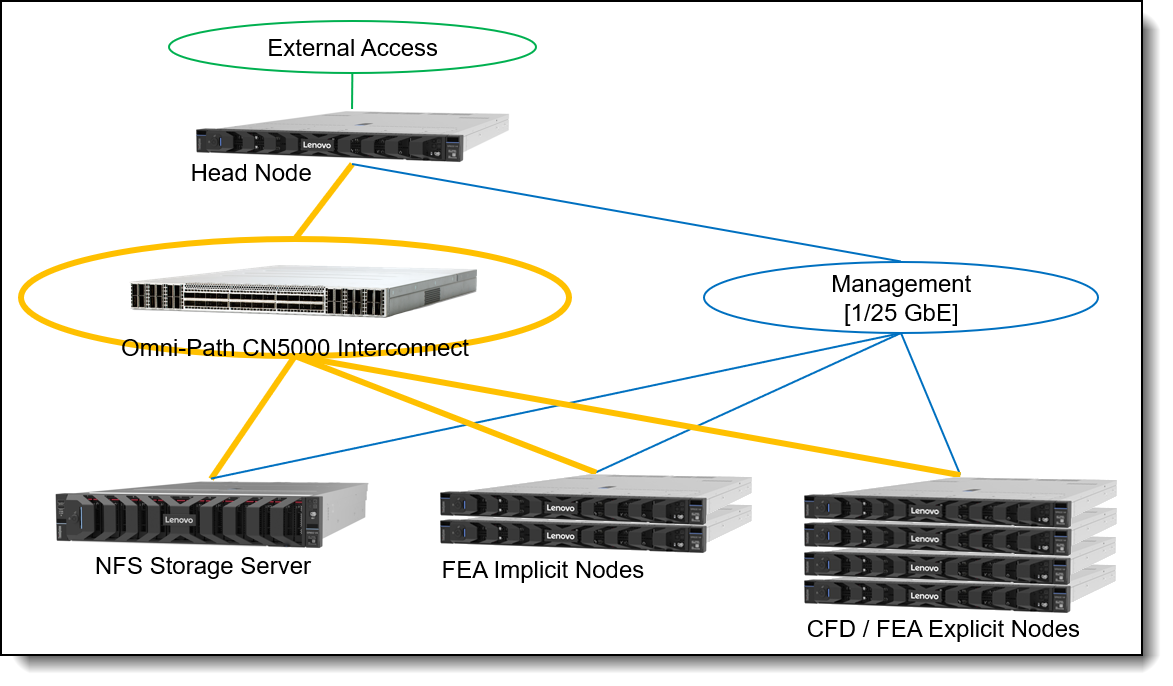
The following figure is an architectural diagram of the CFD Reference Architecture for Entry Clusters.
RA for Entry Clusters - Building Blocks
In this section, we describe the roles and usage of the different Server and Network types, their specific configurations as Intel or AMD CPU based Building Block components, how to scale them to different “T-Shirt sizes” and how to connect them with corresponding networks to a HPC Cluster.
In this section:
Server and Network types
The different server types in a High Performance Computing (HPC) Cluster are referenced here as “Nodes” – which is a common terminology.
- The Head Node is the single point of access to the CFD HPC cluster for users as well as the administrators. The Head Node is connected to the external access network (green), as well as the High Performance Fabric (orange) and the Management Network (blue). Besides the cluster management (e.g. Lenovo Confluent) and resource management/scheduling (e.g. Slurm) software, it also runs the Omni-Path Fabric Manager, which is managing the Omni-Path fabric. Users start and monitor their CAE jobs from this node.
- The NFS Storage Server provides access to a shared NFS file system, which resides on internal NVMe drives. The NFS file system provides a consistent view on the data for all nodes in the system. The NFS file systems are exported over the high-performance Omni-Path High Performance Fabric to all other nodes using IPoIB (IP over IB) protocol.
- The CFD / FEA Explicit Compute Nodes are used for running CFD and/or FEA Explicit workloads. They have a huge number of decent frequency cores, a decent amount of memory and are connected to the Omni-Path High Performance Fabric as well as to a Management Network. The Compute Nodes do not have internal drives for the operating system. Instead, the nodes are booted from the Head Node over the Management Network using the Confluent software. This way, the Compute Node OS images can be kept consistent across the Compute Nodes easily.
- The FEA Implicit Compute Nodes are used for running FEA Implicit workloads. They have a lower number of higher frequency cores, a huge amount of memory and are connected to the Omni-Path High Performance Fabric as well as to a Management Network. The Compute Nodes do not have internal drives for the operating system. Instead, the nodes are booted from the Head Node over the Management Network using the Confluent software. This way, the Compute Node OS images can be kept consistent across the Compute Nodes easily. There is an internal NVMe drive though, which is used for local scratch storage and supports the I/O heavy FEA Implicit jobs while they are running. The input data as well as results though must be stored on the NFS file systems mounted from the NFS Storage Server to guarantee data persistence across re-boots of the Compute Nodes and sharing between different Compute Nodes.
- The Omni-Path High Performance Fabric consists of a Cornelis CN5000 Switch, connected to Cornelis CN5000 SuperNICs in the nodes with high-speed cables. The High Performance Fabric provides 48 ports with a bandwidth of 400 Gbit/s to each server-side adapter. Optionally, a higher number of adapters can be connected using splitter-cables, which connect a 400 Gbit/s port on the CN5000 Switch to two CN5000 SuperNICs at 200 Gbit/s speed each. Up to 32 of the 48 ports can be used with that split-out type of cable, while the remaining 16 ports only support straight 400 Gbit/s cables. That allows for a variety of networking options, optimally adjusted to specific use cases.
- The Management Network was usually provided by a 1 GbE (Gigabit Ethernet) switch. Since the cost for 25 GbE network switches and adapters decreased, the Management Network is trending towards that speed which provides a better user experience when installing systems or for other workloads running on the Ethernet network. In this Reference Architecture we are suggesting a 25 GbE switch for the Management Network.
The External Access Network is provided by the customer network infrastructure and provides connectivity to the CAE HPC cluster via the Head Node. For the Reference Architecture, we assume 25 GbE connections for this network.
Building Block components
The following table describes the configuration of the Server Building Blocks and switches used in the CAE Reference Architecture for Entry Clusters:
Scaling the Building Blocks to HPC Cluster configurations
The suggested "T-shirt sizes" provide a first indication for sizing a system. The Small configuration is providing a cost-effective but minimal functional HPC cluster with the Head Node also providing the NFS storage, while the Medium and Large sizes scale out the number of Compute Nodes (CFD/Explicit FEA as well as Implicit FEA) and have a dedicated NFS Storage Server. The Reference Architecture for Entry Clusters generally uses a 400 Gbit/s connection for each node to the Omni-Path High Performance Fabric.
The X-Large configuration is an example for the maximum system size that can be deployed with a single Cornelis CN5000 Omni-Path Switch and deviates from the minimized infrastructure as provided with the Small, Medium and Large configurations. It uses four Head nodes, two used as redundant Management Nodes and two used as redundant Login Nodes. The four NFS storage servers, each with a 400 Gbit/s connection to the Omni-Path High Performance Fabric, may be considered a placeholder for a larger storage system – four individual NFS storage servers require the administrator to split-up the storage into four separate mount-points, which may not be convenient for the users and harder to manage. Other storage system options though are beyond the scope of this paper.
There are two variants provided for the X-Large configuration: X-Large is using 400 Gbit/s Omni-Path connections to all nodes, while X-Large200 is using 200 Gbit/s Omni-Path for the CFD & Explicit FEA Compute Nodes. This allows the system to scale to an even larger number of Compute Nodes with a single CN5000 Omni-Path Switch. Generally, cutting the available bandwidth by 50% to 200 Gbit/s is not a huge issue for CFD performance – the low latency of the High Performance Fabric is more important than providing the full bandwidth.
As the CN5000 Switches can be deployed in a fabric with different topologies (e.g. fat-tree), much larger deployments are possible – those topologies are described in the next section with scale-out CAE clusters. Those concepts can be applied to this architecture as well for XX-Large or XXX-Large configurations.
The following table shows how the different T-shirt sizes are created from the building blocks described before.
Network connections of the components
This section describes the connections of the servers to the networks in the HPC Cluster:
Omni-Path connections
All servers in the cluster connect to the Cornelis Omni-Path High Performance Fabric through a CN5000 Omni-Path SuperNIC. The Omni-Path fabric speeds up CAE applications by
- Providing low-latency communication between Compute Nodes as the workloads scale-out and job sizes increase. This is especially important for CFD / Explicit FEA applications
- Providing high-bandwidth I/O access to the shared NFS storage using IB over IP protocols. This is especially important for Implicit FEA applications.
The Head Node provides Omni-Path fabric management capabilities through a CN5000 SuperNIC using the Omni-Path Fabric Manager software, which is part of the Cornelis CN5000 OPX Software.
As there are sufficient ports available ton the CN5000 1U 48-port Switch and the CN5000 SuperNIC supports the full speed of 400 Gbit/s, we recommend using CN5000 400G QSFP112 DAC Passive-Straight cables for all node in the T-shirt sizes Small, Medium and Large reference architectures.
In the X-Large200 configuration, we use 400G QSFP- 2x200G QSFP56 DAC Passive-Split cables for the CFD / Explicit FEA nodes, which allows connection of up to 64 of those nodes per CN5000 Omni-Path Switch at 200 Gbit/s bandwidth, in addition to 16 additional servers using the Passive-Straight cable providing 400 Gbit/s of bandwidth. This results in scaling the CAE cluster to a total of 72 HPC Compute Nodes on a single switch with additional ports being available for Storage and Head Nodes.
Management network connections
The management network serves a number of important purposes in the CAE HPC cluster:
- Hardware management: The Head Node (in the role as Administrator Management Node) uses one of his 25GbE Ethernet interfaces for connecting to the Baseboard Management Controllers (BMCs) in the other managed servers through a network port on their internal OCP adapter. This port is shared between the BMC and the operating system on that server using Network Controller Sideband Interface (NC-SI) protocol. In Lenovo servers, the BMC is known as xClarity Controller (XCC). Through this network, the administrator can perform management tasks at the hardware level, like power on/off the servers, open a serial console to the server, update and manage firmware and retrieve telemetry data from the server like temperatures or power consumption. The Lenovo developed Open-Source management software “Confluent” makes use of that network connection and provides a convenient way for managing the whole CAE HPC cluster.
- Operating system boot: The managed systems boot their operating system from the Head Node either for initial installation (for nodes with internal OS drives as the NFS storage server or potential additional Head Nodes, e.g. used in the role as User Login system), or for general operation (for nodes without internal OS drives, which are the CFD / Explicit FEA and Implicit FEA Compute Nodes). The Lenovo Confluent software provides tools for supporting and managing the network boot of the operating system in various ways.
- Node management: The management network is also used for managing the cluster at the operating system level. The Lenovo Confluent management software helps with setting up secure connections between the Head Node and the managed operating systems on the nodes and provides tools for parallel management of multiple or even all nodes from a single command line.
- Infrastructure management: The CN5000 Omni-Path Switch provides a 1GbE management port that can also be added to the Management Network, e.g. for retrieving switch telemetry data (the Fabric Management itself though is using the CN5000 SuperNIC on the Head Node). Also managed PDUs may be connected to the Management Network for power control and monitoring. As we use a 25GbE switch with SFP28 ports for the Management Network, RJ45 to SFP+ adapters are needed for connecting the RJ45 connections of the 1GbE cables to the switch ports.
RA for Entry Clusters – Intel CPU-based
This section describes how the Intel CPU-based server Building Blocks for Entry Clusters look like and provides a detailed list of the required components:
Lenovo ThinkSystem SR630 V4
Lenovo ThinkSystem SR630 V4 air-cooled 1U servers are used as Head Nodes in a User Login and/or Administrator Management role as well as HPC Compute Nodes in the CAE Reference Architectures for Entry Clusters using Intel-CPU based servers.
The Lenovo ThinkSystem SR630 V4 is a 2-socket 1U rack server providing industry-leading reliability, management, and security, as well as maximizing performance and flexibility for future growth. With two Intel Xeon 6700-series processors, the SR630 V4 is designed for high density and scale-out workloads in various customer segments.
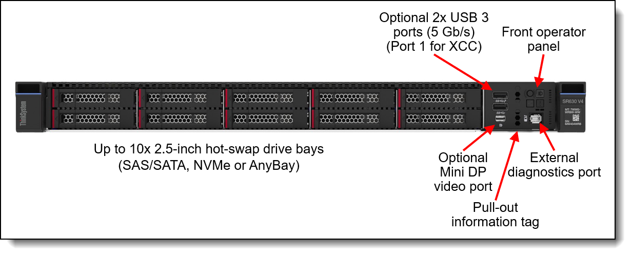
Figure 7. Front view of the SR630 V4 with 2.5-inch drive bays
It provides several different configuration options. In the Reference Architectures we use a chassis supporting up to 10x 2.5-inch hot-swap drives on the front.
At the back side, the SR630 V4 provides external connectivity through up to 3 PCIe (1 Full Height and 2 Low Profile) slots and 2 OCP slots.
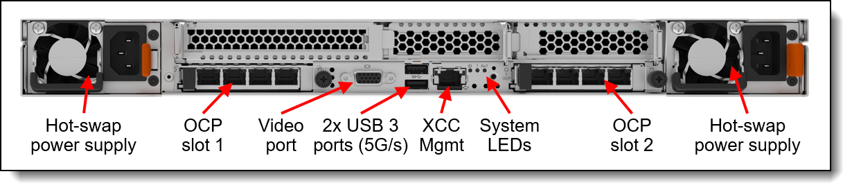
Figure 8. Rear view of the SR630 V4 with three PCIe slots
The SR630 V4 product guide provides a more detailed description of the server:
https://lenovopress.lenovo.com/lp1971-thinksystem-sr630-v4-server
Lenovo ThinkSystem SR650 V4
Lenovo ThinkSystem SR650 V4 air-cooled 2U servers are used as Storage Nodes in the CAE Reference Architectures for Entry Clusters using Intel-CPU based servers. They are also an option, if Head Nodes require additional networking connectivity, as they provide additional PCIe slots compared to the 1U servers.
The Lenovo ThinkSystem SR650 V4 is a 2-socket 2U rack server providing industry-leading reliability, management, and security, as well as maximizing performance and flexibility for future growth. With two Intel Xeon 6700-series, the SR650 V4 is designed for high density and scale-out workloads.
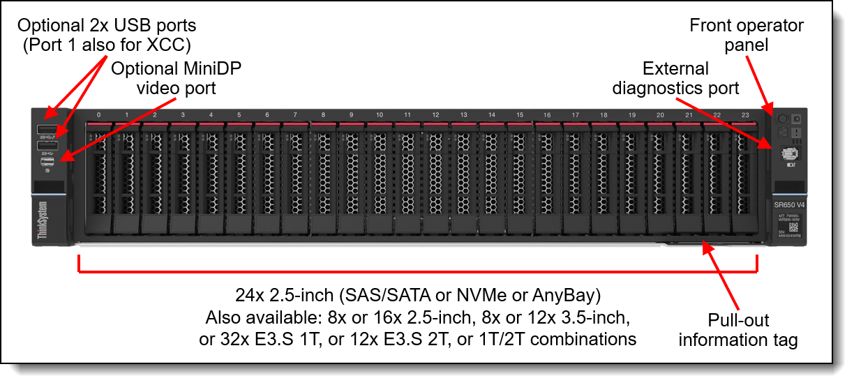
Figure 9. Front view of the ThinkSystem SR650 V4 with 2.5-inch drive bays
It provides several different configuration options. In the Reference Architectures we use a chassis with a NVMe backplane supporting 8 NVMe drives, connected to an internal HW adapter supporting Intel VROC RAID.
The SR650 V4 provides external connectivity through up to 10 PCIe slots and 2 OCP slots at the back side. In the Reference Architecture, less PCIe slots are needed and hence the number of PCIe slots provided is below the maximum.
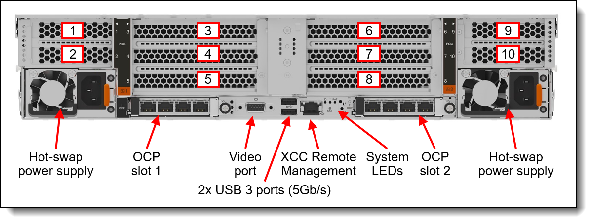
Figure 10. Rear view of the SR650 V4 (configuration with ten PCIe slots)
The SR650 V4 product guide provides a more detailed description of the server:
https://lenovopress.lenovo.com/lp2127-thinksystem-sr650-v4-server
Bill of Materials for Intel servers
The table lists the Bill of Materials (BOM) for the SR630 V4 and SR650 V4. The BOM include only the significant parts – other parts like Risers or Power supplies have been removed for better readability. The Lenovo sales configurators DCSC and x-config help to create a valid configuration from the following BOM lists.
Racks and Power Distribution Units are not included in the BOM assuming those are provided by the customer separately.
Adjust the BOM to your specific situation as needed (e.g. cable lengths).
RA for Entry Clusters - AMD CPU-based
This section describes how the AMD CPU-based server Building Blocks for Entry Clusters look like and provides a detailed list of the required components.
Lenovo ThinkSystem SR645 V3
Lenovo ThinkSystem SR645 V3 air-cooled 1U servers are used as Head Nodes in a User Login and/or Administrator Management role as well as HPC Compute Nodes in the CAE Reference Architectures for Entry Clusters using AMD CPU-based servers.
The Lenovo ThinkSystem SR645 V3 is a 2-socket 1U server supporting the 5th Gen AMD EPYC 9005 "Turin" family of processors. With up to 160 cores per processor and support for the new PCIe 5.0 standard for I/O, the SR645 V3 offers great two-socket server performance in a 1U form factor.
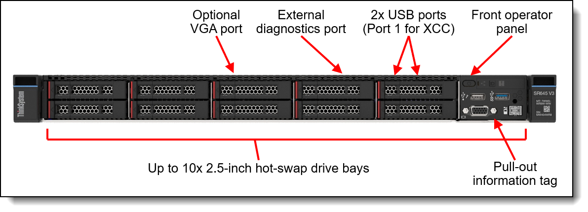
Figure 11. Front view of the ThinkSystem SR645 V3 with 2.5-inch drive bays
It provides several different configuration options. In the Reference Architectures we use a chassis supporting up to 10x 2.5-inch hot-swap drives on the front.
In the configuration used in the Reference Architectures, the SR645 V3 provides external connectivity through up to 2 PCIe (1 Full Height and 1 Low Profile) slots and 1 OCP slots at the back side.
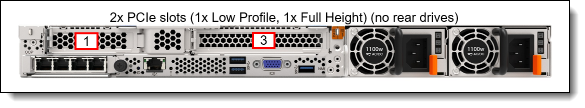
Figure 12. Rear view of the ThinkSystem SR645 V3 with two PCIe slots
The SR645 V3 product guide provides a more detailed description of the server:
https://lenovopress.lenovo.com/lp1607-thinksystem-sr645-v3-server
Lenovo ThinkSystem SR665 V3
Lenovo ThinkSystem SR665 V3 air-cooled 2U servers are used as Storage Nodes in the CAE Reference Architectures for Entry Clusters using AMD-CPU based servers. They are also an option, if Head Nodes require additional networking connectivity, as they provide additional PCIe slots compared to the 1U servers.
The Lenovo ThinkSystem SR665 V3 is a 2-socket 2U server supporting the 5th Gen AMD EPYC 9005 "Turin" family of processors. With up to 160 cores per processor and support for the new PCIe 5.0 standard for I/O, the SR665 V3 offers the ultimate in two-socket server performance in a 2U form factor.
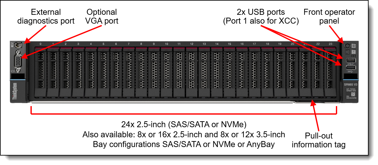
Figure 13. Front view of the ThinkSystem SR665 V3 with 2.5-inch drive bays
It provides several different configuration options. In the Reference Architectures we use a chassis with an NVMe backplane supporting 8 NVMe drives, connected to an internal RAID adapter.
The SR665 V3 provides external connectivity through up to 8 PCIe slots and 1 OCP slot at the back side. In the Reference Architecture, less PCIe slots are needed and hence the number of PCIe slots provided is below the maximum.

Figure 14. Rear view of the SR665 V3 (configuration with 8 PCIe slots)
The SR665 V3 product guide provides a more detailed description of the server:
https://lenovopress.lenovo.com/lp1608-thinksystem-sr665-v3-server
Bill of Materials for AMD servers
The table lists the Bill of Materials (BOM) for the SR645 V3 and SR665 V3. The BOM include only the significant parts – other parts like Risers or Power supplies have been removed for better readability. The Lenovo sales configurators DCSC and x-config help to create a valid configuration from the following BOM lists.
Racks and Power Distribution Units are not included in the BOM assuming those are provided by the customer separately.
Adjust the BOM to your specific situation as needed (e.g. cable lengths).
RA for Scale-Out Clusters - Overview
This CAE Reference Architectures for Scale-Out Clusters are purpose-built for accelerating CAE and Computational Fluid Dynamics (CFD) workloads across a wide range of industries and applications, utilizing parallelism across many Compute Nodes. They use Lenovo Neptune direct-water-cooling technology for providing maximum performance with optimal use of energy.
There are two versions of this Reference Architecture:
- Intel Xeon 6900-series CPU-based Scalable Unit (SU) Reference Architecture
- AMD 5th Gen EPYC CPU-based Scalable Unit (SU) Reference Architecture
For each dual-socket Compute Node, a network bandwidth of 200 Gbit/s to the Cornelis CN5000 Omni-Path High Performance Fabric is planned. Omni-Path can provide 400 Gbit/s bandwidth to each Compute Node adapter with straight cables. For CAE workloads, the Omni-Path High Performance Fabric bandwidth to the Compute Nodes is generally less important than the low-latency performance that Omni-Path provides. Hence the use of splitter cables providing 200 Gbit/s bandwidth per Compute Node is more cost efficient for scale-out, as it requires less CN5000 Switches and less cables compared to a solution with 400 Gbit/s per Compute Node.
Management or Login servers as well as storage are out-of-scope for this Reference Architectures. Examples can be found in the previous RA for Entry Clusters section but should be adjusted according to the specific needs.
For storage in a CAE scale-out environment, a higher performing and scalable parallel file system solution like Lenovo DSS-G is recommended compared to a single NFS server. Lenovo Distributed Storage Solution for IBM Storage Scale (DSS-G) is a software-defined storage (SDS) solution for dense scalable file and object storage suitable for high-performance and data-intensive environments. DSS-G combines the performance of Lenovo ThinkSystem servers, Lenovo storage enclosures, and industry leading IBM Storage Scale software, to offer a high performance, scalable building block approach to modern storage needs.
Lenovo plans to enable a direct connection of DSS-G building blocks to the Cornelis CN5000 Omni-Path High Performance Fabric in 2026. Until then, a connection of DSS-G storage to the system using Ethernet Networks or a gateway solution is a possibility. Please contact your Lenovo or Partner representative for a recommended solution for your specific environment and check the DSS-G product guide for more information:
https://lenovopress.lenovo.com/lp1842-lenovo-dss-g-thinksystem-v3
RA for Scale-Out Clusters - Intel CPU-based
Leveraging Lenovo ThinkSystem SC750 V4 Neptune DWC servers powered by Intel Xeon 6900-series processors, this architecture integrates advanced direct water-cooling technology to deliver high performance with exceptional energy efficiency. With high-speed Omni-Path High Performance Fabric and MRDIMM memory technology, the solution provides the computational scale and bandwidth required to handle complex CFD simulations—enabling faster runtimes, greater model fidelity, and accelerated innovation.
Scalable Unit (SU) building block design - Intel servers
This Reference Architecture is built on a Scalable Unit (SU) structure, with 24 SC750 V4 dual-node trays, 48 Compute Nodes and 96 CPUs per SU, with 200 Gbit/s bandwidth from each Compute Node to the Omni-Path High Performance Fabric. It scales up to 46 Scalable Units with 2208 servers and 4408 CPUs within a standard FAT Tree Network Topology, with two CN5000 Omni-Path Switches being reserved for Management and Login Nodes as well as storage.
With alternative network topologies such as Megafly, the architecture has the potential to scale exponentially, so there are options available if the cluster needs to scale further.
Each Scalable Unit comprises a single compute rack equipped with one high-speed CN5000 Omni-Path leaf switch as well as Ethernet switches for hardware management and operating system boot. This SU is purpose-built for seamless scalability, offering on-demand growth to support CFD simulations of any resolution or complexity.
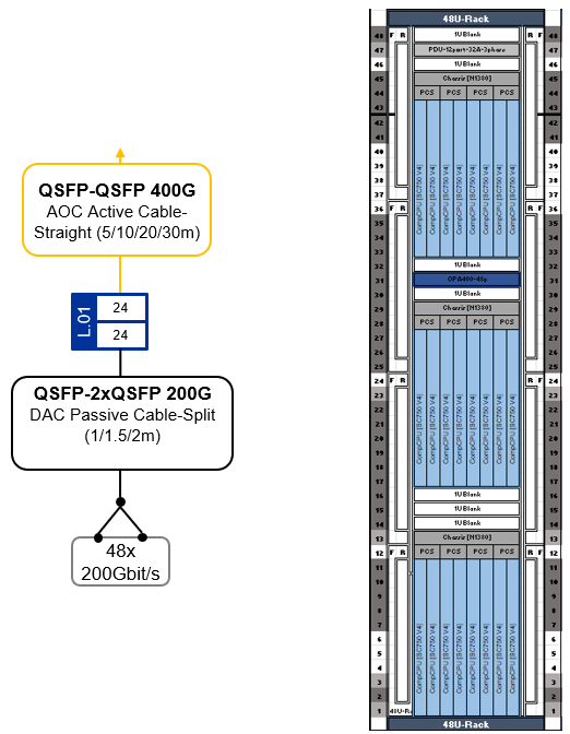
Figure 15. SU for 48 CFD Compute Nodes in 24 Lenovo SC750 V4 trays
Scaling-out the SUs with Omni-Path Fat-Tree topology - Intel servers
This Reference Architecture employs a high-speed network utilizing the Cornelis CN5000 Omni-Path High Performance Fabric with 200 Gbit/s bandwidth per Compute Node. This Omni-Path fabric is implemented in a Fat-Tree topology with up to 24 spine and 48 leaf switches, enabling scalability up to 2304 CN5000 Omni-Path SuperNICs at 200 Gbit/s bandwidth. Each leaf switch connects to the spine switches with 24 * 400 Gbit/s uplinks (Omni-Path cable-straight).
Of the up to 48 leaf switches, two are reserved for Management/Login nodes as well as storage I/O connectivity, supporting up to 96 Omni-Path SuperNICs at 200 Gbit/s bandwidth using Omni-Path cable-split.
The remaining up to 46 leaf switches support up to 2208 CAE Compute Nodes with 4416 CPUs at 200 Gbit/s bandwidth using Omni-Path cable-split.
The following table shows how the number of Spine Switches and uplink/downlink ports scales with the number of Scalable Units (SUs) in a configuration.
The first row in the table with just a single SU defines a “special case”, which is not actually a scale-out cluster but uses only a single CN5000 Omni-Path Switch. There is no need for a Spine Layer in this single SU configuration, and Management/Login as well as Storage can be connected to the same switch, like what we described in the RA for Entry Clusters section earlier.
The Omni-Path High Performance Fabric topology provides a solid network High Performance Fabric foundation for massive scale-out CFD solutions, addressing the needs for scalability, high bandwidth, and low latency, ensuring robust performance for complex simulations and models.
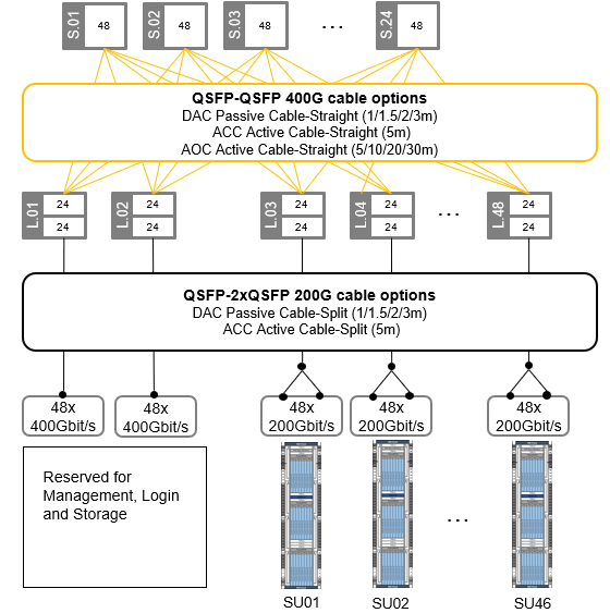
Figure 16. Omni-Path Fat-Tree topology for up to 2208 * Compute Nodes @200Gbit/s
Each Scalable Unit consists of a single compute rack housing 48 nodes shared across 24 Lenovo ThinkSystem SC750 V4 dual-node compute trays. Each compute tray is equipped with two high-speed CN5000 Omni-Path SuperNICs (one per Compute Node). With Omni-Path split cables, the two CN5000 SuperNICs in a tray are connected at 200 Gbit/s to a single 400 Gbit/s port on the CN5000 Omni-Path Switch, cutting the network bandwidth to 50%. Performance testing has shown that this reduction has a minimal impact on CFD workloads, with less than a 10% performance drop observed even at large scales.
This streamlined approach offers a cost-effective solution for scaling CPU and memory-intensive workloads. By maintaining a balanced design, customers can accurately scale their workload when CPU and memory tasks heavily outweigh inter-node communication requirements. This optimized configuration results in significant cost savings while delivering optimal price and performance.
Cluster management is usually done over Ethernet, and the SC750 V4 offers multiple options. It comes with 25GbE SFP28 Ethernet ports, a Gigabit Ethernet port, and a dedicated XClarity Controller (XCC) port. For connecting to the XCC, there is also a second path through the N1380 enclosure Systems Management Module (SMM). These can be customized based on cluster management and workload needs.
For stable environments where the Operating System is installed on local hard drives and there are infrequent OS changes, the single Gigabit Ethernet port is sufficient for the Management Network. A CAT5e or CAT6 cable per node can use Network Controller Sideband Interface (NC-SI) for remote out-of-band and cluster management over one wire.
For massive scale-out clusters though, it is recommended to boot the Operating System from a centralized Management Server instead of installing it on local drive. This way, it is easy to keep the Operating System image consistent across the CAE HPC cluster. The Confluent management Software, developed by Lenovo, provides a toolkit for Compute Nodes in a diskless way. For this kind of diskless installations, as well as for higher bandwidth needs or frequent updates, the 25Gb Ethernet interfaces offer a better solution, including sideband communication to the XCC.
For this CAE Reference Architecture, the 25Gbit Ethernet interfaces of each SC750 V4 compute tray are linked to a 25 GbE Management Leaf switch, ensuring fast Operating Boot over the network and connectivity for the Compute Nodes' cluster management. For out-of-band management, access to the SC750 V4 xClarity Controller (XCC) and N1380 enclosure systems management modules (SMM) is provided through 1Gbit Ethernet connections to a centralized Hardware Management Ethernet Switch.
Lenovo ThinkSystem N1380 chassis
The ThinkSystem N1380 Neptune chassis is the core building block, built to enable exascale-level performance while maintaining a standard 19-inch rack footprint. It uses liquid cooling to remove heat and increase performance and is engineered for the next decade of computational technology.
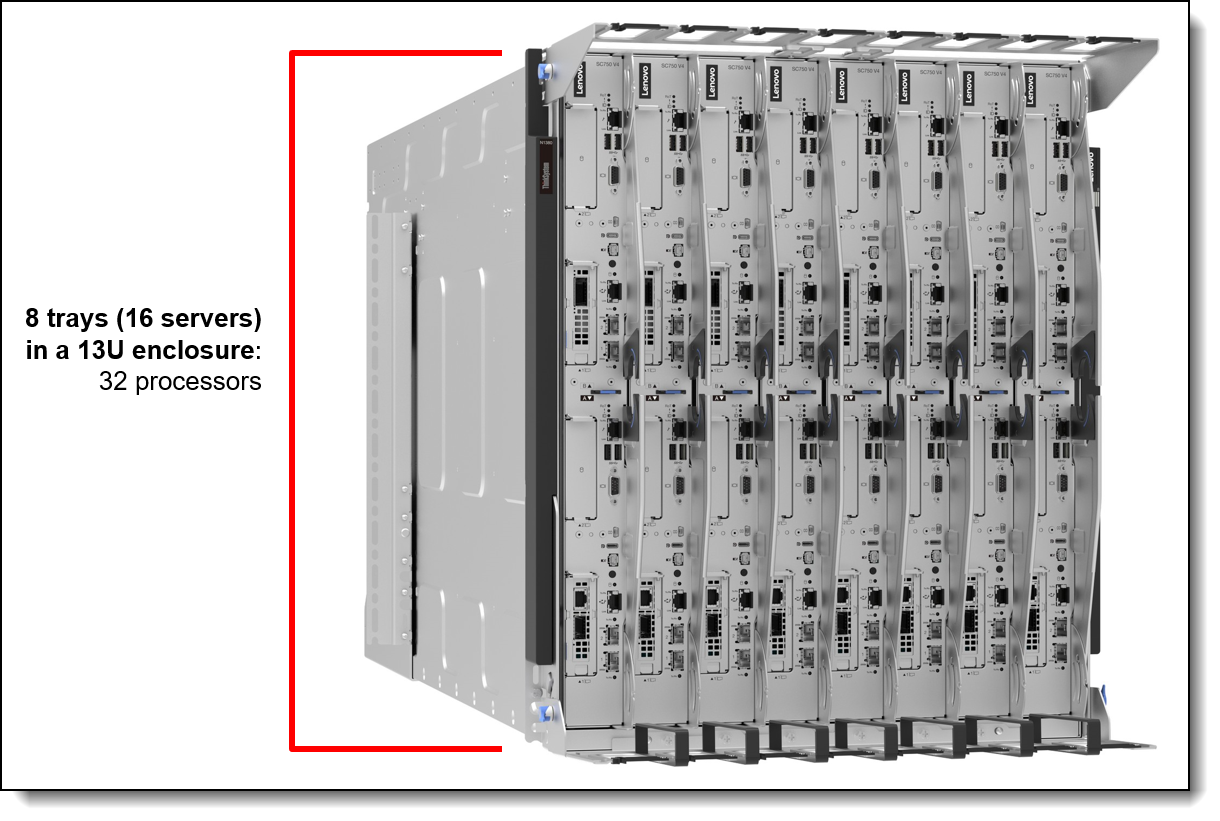
Figure 17. Lenovo ThinkSystem N1380 Enclosure
N1380 features an integrated manifold that offers a patented blind-mate mechanism with aerospace-grade drip-less connectors to the compute trays, ensuring safe and seamless operation. The unique design of the N1380 eliminates the need for internal airflow and power-consuming fans. As a result, it achieves a reduction in typical data center power consumption by up to 40% compared to similar air-cooled systems.
This newly developed enclosure incorporates up to four ThinkSystem 15kW Titanium Power Conversion Stations (PCS). These stations are directly fed with high current three-phase power and supply power to an internal 48V busbar, which in turn powers the compute trays. The PCS design is a game-changer, merging power conversion, rectification, and distribution into a single package. This is a significant transformation from traditional setups that require separate rack PDUs, additional cables and server power supplies, resulting in best-in-class efficiency. In specific CPU configurations, the PCS can be optimized to only require 2 PCS per chassis whilst still fully powering the nodes for performance.
Each 13U Lenovo ThinkSystem N1380 Neptune enclosure houses eight Lenovo ThinkSystem SC-series Neptune trays. Up to three N1380 enclosures fit into a standard 19" rack cabinet, packing 24 trays into just two 60x60 datacenter floor tiles.
Lenovo ThinkSystem SC750 V4 dual-server tray
The ThinkSystem SC750 V4 Neptune node is the next-generation high-performance server based on the sixth generation Lenovo Neptune direct water cooling platform.
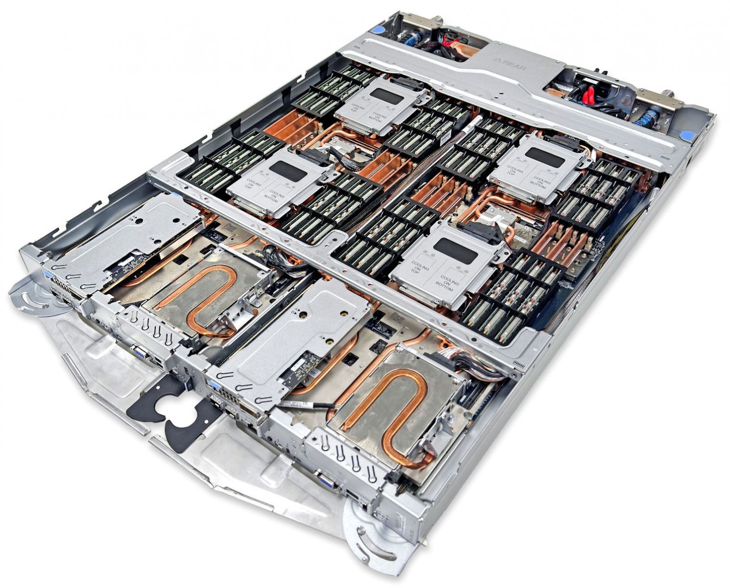
Figure 18. Lenovo ThinkSystem SC750 V4 Neptune Server Tray
Supporting the Intel Xeon 6900P-series, the ThinkSystem SC750 V4 Neptune stands as a powerhouse for demanding HPC workloads. Its industry-leading direct water-cooling system ensures steady heat dissipation, allowing CPUs to maintain accelerated operation and achieve up to a 10% performance enhancement.
With 12 channels of high-speed DDR5 RDIMM or an impressive 8800MHz high-bandwidth MRDIMM capability, it excels in memory bandwidth-intensive workloads, positioning it as a preferred choice for engineering and meteorology applications like Fluent, STAR-CCM+, OpenFOAM, WRF, and ICON.
Completing the package with support for high-performance NVMe and high-speed, low-latency networking with the latest InfiniBand, Omni-Path, and Ethernet choices, the SC750 V4 is your all-in-one solution for HPC workloads.
At its core, Lenovo Neptune applies 100% direct warm-water cooling, maximizing performance and energy efficiency without sacrificing accessibility or serviceability. The SC750 V4 is installed into the ThinkSystem N1380 Neptune enclosure which itself integrates seamlessly into a standard 19" rack cabinet. Featuring a patented blind-mate stainless steel dripless quick connection, SC750 V4 node trays can be added “hot” or removed for service without impacting other node trays in the enclosure.
This modular design ensures easy serviceability and extreme performance density, making the SC750 V4 the go-to choice for compute clusters of all sizes - from departmental/workgroup levels to the world’s most powerful supercomputers – from Exascale to Everyscale.
Intel Xeon 6 processors with P-cores are optimized for high performance per core. With more cores, double the memory bandwidth, and AI acceleration in every core, Intel Xeon 6 processors with P-cores provide twice the performance for the widest range of workloads, including HPC and AI.
Domains such as CAE/CFD and weather/climate modeling present a more balanced performance profile - demanding both high compute throughput and substantial memory bandwidth. Simply increasing core counts can lead to diminishing returns unless accompanied by improvements in memory access speed, latency, and power delivery. The Intel Xeon 6900 series address these challenges by expanding the thermal design power (TDP) to 500 watts, which, when coupled with Lenovo Neptune cooling, helps to sustain or even boost CPU frequencies under heavy loads.
Additionally, support for 12 memory channels and compatibility with DDR5-6400 MHz and MRDIMM-8800 MHz memory types significantly increases memory bandwidth, ensuring that high-core-count systems remain efficient and scalable for memory-intensive workloads. Reflecting these architectural advantages, CFD workloads from Fluent, STAR-CCM+, and OpenFOAM have observed over 2.4x faster computational times on average when running on Intel Xeon 6900 P-core processors compared to the previous generation - demonstrating the real-world impact of these enhancements on simulation throughput and productivity.
In this Reference Architecture, each Compute Node is equipped with two Intel Xeon 6960P CPUs, each comprising 72 Xeon6 P-cores. This configuration provides 144 Xeon6 P-cores and 1.5TB of MRDIMM RAM per node, making the SC750 V4 highly suited for core and RAM-intensive tasks. Utilizing high-speed, low-latency Cornelis CN5000 Omni-Path SuperNICs at 200 Gbit/s, the SC750 V4, when paired with Intel Xeon6, offers exceptional scalability for the most demanding parallel MPI jobs.
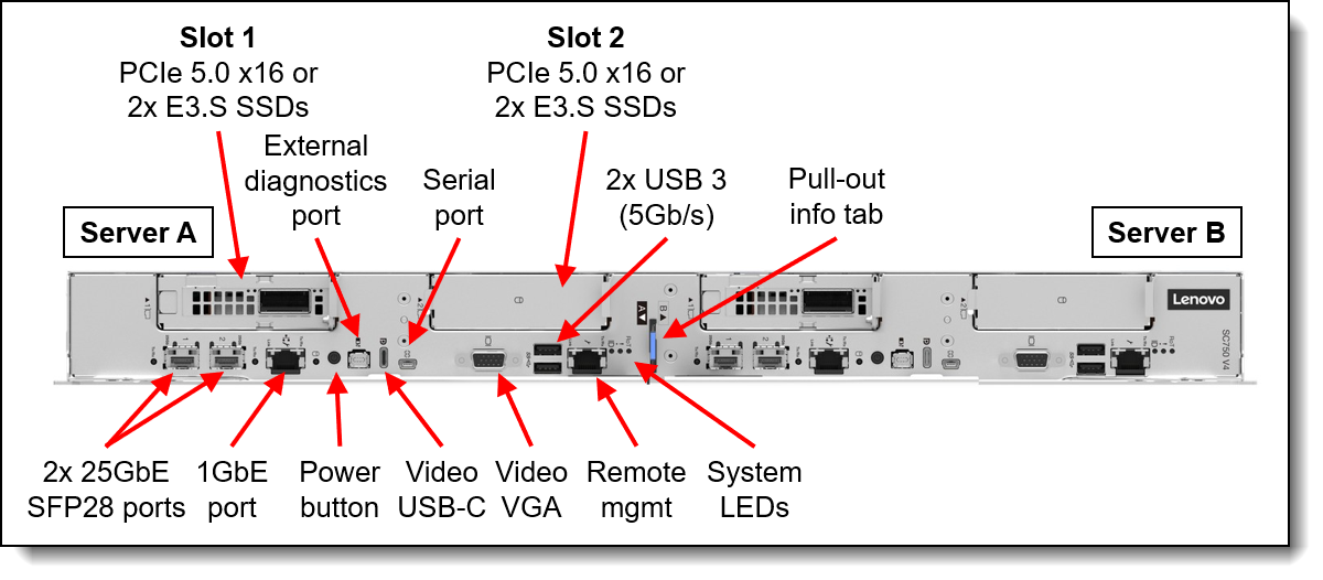
Figure 19. SC750 V4 Front View with Management Ports
The SC750 V4 integrates the XCC through the Data Center Secure Control Module (DC-SCM) I/O board. This module also includes a Root of Trust module (NIST SP800-193 compliant), USB 3.2 ports, a VGA port, and MicroSD card capability for additional storage with the XCC, offering firmware storage options up to 4GB, including N-1 firmware history.
The N1380 enclosure features a System Management Module 3 (SMM) at the rear, managing both the enclosure and individual servers through a web browser or Redfish/IPMI 2.0 commands. The SMM provides remote connectivity to XCC controllers, node-level reporting, power control, enclosure power management, thermal management, and inventory tracking.
Bill of Materials (BOM) for Intel CPU-based SU
The following Bill of Materials (BOM) include only the significant parts of the Scalable Unit (SU) building block – other parts like Risers or Power cables have been removed for better readability.
The Lenovo sales configurators DCSC and x-config will help to create a valid configuration from the BOM list.
In addition to the Compute Node SUs as described in this BOM, there are central components that need to be provided, for example
- Omni-Path leaf switches (for management/login/storage) and spine switches
- Ethernet leaf switches (for management/login/storage) and core switches
- Management, login and storage systems
Also adjust the SU BOM to your specific situation as needed (e.g. cable lengths from the SU to spine/core switches are 30m in this BOM – shorter or longer cable lengths may be required for connecting to the central spine/core switches are needed, depending on the location of the racks in the data center).
RA for Scale-Out Clusters - AMD CPU-based
Leveraging Lenovo ThinkSystem SD665 V3 Neptune DWC servers powered by two 5th Gen AMD EPYC processors, this architecture integrates advanced direct water-cooling technology to deliver high performance with exceptional energy efficiency. With high-speed Omni-Path High Performance Fabric, the solution provides the computational scale and bandwidth required to handle complex CFD simulations—enabling faster runtimes, greater model fidelity, and accelerated innovation.
Scalable Unit (SU) building block design - AMD servers
This Reference Architecture is built on a Scalable Unit (SU) structure, with 72 SD665 V3 dual-node trays, 144 Compute Nodes and 288 CPUs per SU, with 200 Gbit/s bandwidth from each Compute Node to the Omni-Path High Performance Fabric. This architecture scales up to 15 Scalable Units with 2160 servers and 4320 CPUs within a standard FAT Tree Network Topology, with two CN5000 Switches being reserved for Management and Login Nodes as well as storage.
With alternative network topologies such as Megafly, the architecture has the potential to scale exponentially, so there are options available if the cluster needs to scale further.
Each Scalable Unit comprises two compute racks equipped with three high-speed Omni-Path leaf switches as well as Ethernet switches for hardware management and operating system boot. This SU is purpose-built for seamless scalability, offering on-demand growth to support CFD simulations of any resolution or complexity.
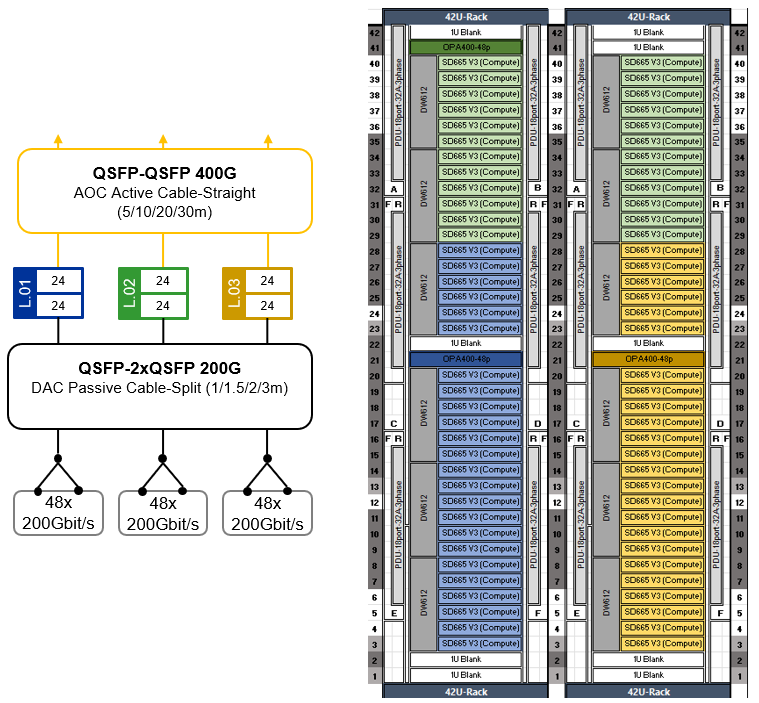
Figure 20. SU for 144 CFD Compute Nodes in 72 Lenovo ThinkSystem SD665 V3 trays
Scaling-out the SUs with Omni-Path Fat-Tree topology - AMD servers
This Reference Architecture employs a high-speed network utilizing the Cornelis CN5000 Omni-Path High Performance Fabric with 200 Gbit/s bandwidth per Compute Node. This Omni-Path fabric is implemented in a Fat-Tree topology with up to 24 spine and 47 leaf switches, enabling scalability up to 2256 CN5000 Omni-Path SuperNICs at 200 Gbit/s bandwidth. Each leaf switch connects to the spine switches with 24 * 400 Gbit/s uplinks (Omni-Path cable-straight).
Of the up to 47 leaf switches, two are reserved for Management/Login nodes as well as storage I/O connectivity, supporting up to 96 Omni-Path SuperNICs at 200 Gbit/s bandwidth using Omni-Path cable-split.
The remaining up to 45 leaf switches support up to 2160 CAE Compute Nodes with 4320 CPUs at 200 Gbit/s bandwidth using Omni-Path cable-split.
The following table shows how the number of Spine Switches and uplink/downlink ports scale with the number of Scalable Units (SUs) in a configuration.
The Omni-Path High Performance Fabric topology provides a solid network High Performance Fabric foundation for massive scale-out CFD solutions, addressing the needs for scalability, high bandwidth, and low latency, ensuring robust performance for complex simulations and models.
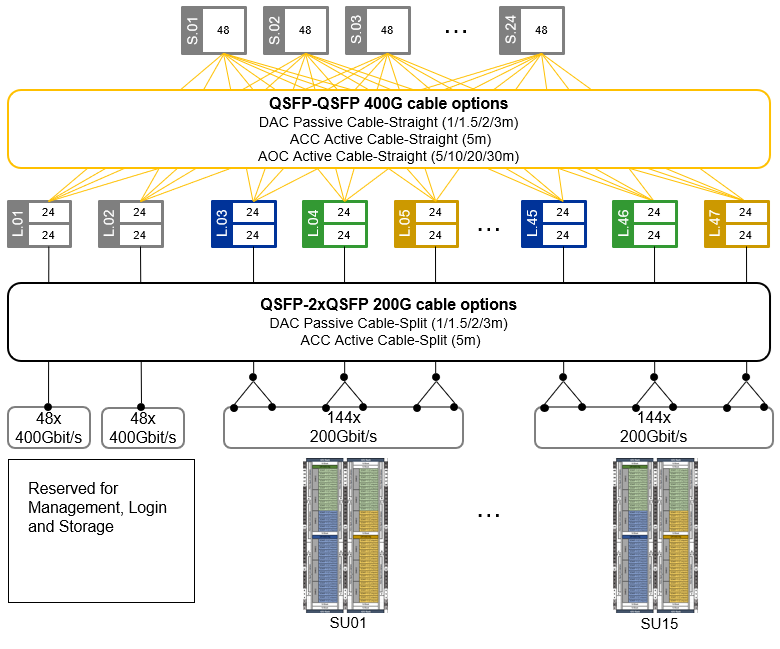
Figure 21. Omni-Path Fat-Tree topology for up to 2160 * Compute Nodes @200Gbit/s
Each Scalable Unit consists of two compute rack housing 144 Compute Nodes shared across 72 Lenovo ThinkSystem SD665 V3 dual-node compute trays. Each compute tray is equipped with two high-speed CN5000 Omni-Path SuperNICs (one per Compute Node). With Omni-Path split cables, the two CN5000 adapters in a tray are connected at 200 Gbit/s to a single 400 Gbit/s port on the CN5000 Omni-Path Switch, cutting the network bandwidth to 50%. Performance testing has shown that this reduction has a minimal impact on CFD workloads, with less than a 10% performance drop observed even at large scales.
This streamlined approach offers a cost-effective solution for scaling CPU and memory-intensive workloads. By maintaining a balanced design, customers can accurately scale their workload when CPU and memory tasks heavily outweigh inter-node communication requirements. This optimized configuration results in significant cost savings while delivering optimal price and performance.
Cluster management is usually done over Ethernet, and the SD665 V3 offers multiple options. It comes with 25GbE SFP28 Ethernet ports and a Gigabit Ethernet port – one of those can optionally be shared with the XClarity Controller (XCC). For connecting to the XCC, there is also a second path through the DW612S enclosure Systems Management Module (SMM). These can be customized based on cluster management and workload needs.
For stable environments where the Operating System is installed on local hard drives and there are infrequent OS changes, the single Gigabit Ethernet port is sufficient for the Management Network. A CAT5e or CAT6 cable per node can use Network Controller Sideband Interface (NC-SI) for remote out-of-band and cluster management over one wire.
For massive scale-out clusters though, it is recommended to boot the Operating System from a centralized Management Server instead of installing it on local drive. This way, it is easy to keep the Operating System image consistent across the CAE HPC cluster. The Confluent management Software, developed by Lenovo, provides a toolkit for Compute Nodes in a diskless way. For this kind of diskless installations, as well as for higher bandwidth needs or frequent updates, the 25Gb Ethernet interfaces offer a better solution, including sideband communication to the XCC.
For this CAE Reference Architecture, the 25Gbit Ethernet interfaces of each SD665 V3 dual-node trays are linked to a 25 GbE Management Leaf switch, ensuring fast Operating Boot over the network and connectivity for the Compute Nodes' cluster management. For out-of-band management, access to the SD665 V3 xClarity Controller (XCC) and DW612S enclosure systems management modules (SMM) is provided through 1Gbit Ethernet connections to a centralized Hardware Management Ethernet Switch.
Lenovo ThinkSystem DW612S Enclosure
The Direct-Water-Cooled (DSC) Lenovo ThinkSystem DW612S enclosure provides the power and water-cooling infrastructure for the SD665 V3 dua-node compute trays. It provides 6 horizontal slots on the front side for up to 6 compute trays, which connect to the enclosure mid-plane and enclosure-internal water manifold through patented stainless-steel drip-less quick connectors. Trays can be removed and inserted into the enclosure without impact on the operation of the other trays.
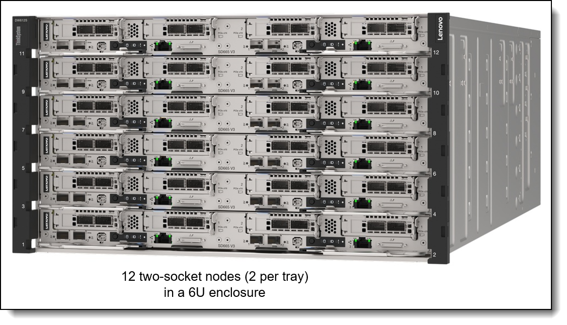
Figure 22. ThinkSystem DW612S enclosure front view
At the backside of the enclosure, there is space for either six or eight air-cooled power supplies or three direct-water-cooled AC power supplies. There is also a System Management Module (SMM) at the back, which allows remote management of the enclosure (e.g. providing power telemetry or the ability for power on/off or a virtual re-seat of individual trays) as well as an internal network connection to the Management Modules (xClarity Controller -XCC) in the Compute Trays.

Figure 23. ThinkSystem DW612S enclosure rear view
For this reference architecture, six ThinkSystem 2600W 230V Titanium Hot-Swap Gen2 Power Supplies per DW612S enclosure are used. That provides sufficient power for a N+1 redundant power configuration with over-subscription. (Oversubscription implies, that if one power supply fails, the Compute Nodes may be throttled if under heavy load.)
Lenovo ThinkSystem SD665 V3
The Lenovo ThinkSystem SD665 V3 dual-node tray is designed for High Performance Computing (HPC), large-scale cloud, heavy simulations and modeling.
It supports Lenovo Neptune™ Direct Water Cooling (DWC) technology as well as workloads from technical computing, grid deployments, analytics, and is ideally suited for fields such as research, life sciences, energy, simulation, and engineering.
The unique design of ThinkSystem SD665 V3 provides the optimal balance of serviceability, performance, and efficiency.
By using a standard rack with the ThinkSystem DW612S enclosure equipped with patented stainless-steel drip-less quick connectors, the SD665 V3 provides easy serviceability and extreme density that is well suited for clusters ranging from small enterprises to the world's largest supercomputers.
The Lenovo Neptune™ direct liquid cooling doesn't use risky plastic retrofitting but custom designed copper water loops, so you have peace of mind implementing a platform with liquid cooling at the core of the design.
Compared to other technology, the ThinkSystem SD665 V3 direct water cooling:
- Reduces data center energy costs by up to 40%
- Increases system performance by up to 10%
- Delivers up to 95% heat removal efficiency
- Creates a quieter data center with its fan-less design
- Enables data center growth without adding computer room air conditioning
Designed to run the highest core-count 5th Generation AMD EPYC™ Processor, the SD665 V3 powers through demanding HPC workloads. Because water cooling removes more heat constantly, CPUs can run in accelerated mode nonstop, getting up to 10% greater performance from the CPU.
The 5th Generation AMD EPYC™ Processors combine both superior memory bandwidth capacity and core-counts that can increase performance across all HPC workloads.
The 5th Generation AMD EPYC™ Processors excel in HPC application and workloads that are memory sensitive, scale well to multiple cores, and are not highly vectorized applications within the manufacturing/computer-aided engineering (CAE) and weather/climate verticals like OpenFOAM, ANSYS Fluent, ANSYS CFX, ANSYS LS-DYNA, Siemens STAR-CCM+, MOM5, and WRF.
For even greater system performance, the SD665 V3 uses 6400MHz DDR5 memory and supports NVMe storage, high-speed NDR InfiniBand.
The Lenovo ThinkSystem SD665 V3 is enabled with Lenovo HPC & AI Software Stack, so, you can support multiple users and scale within a single cluster environment.
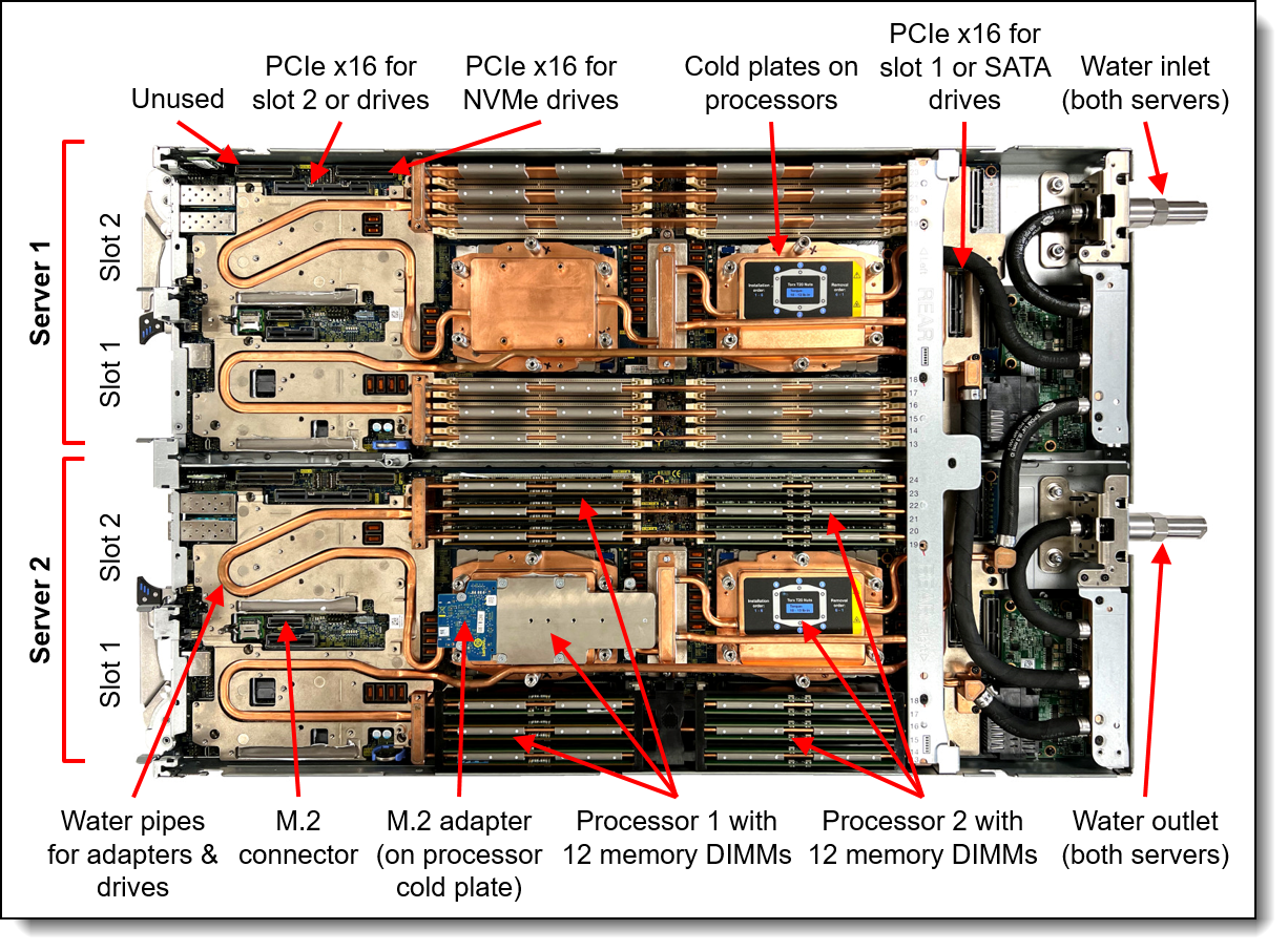
Figure 24. ThinkSystem SD665 V3 dual-server tray – top view
Each of the two side-by-side servers / nodes in the SD665 V3 tray supports two fifth-generation AMD EPYC processors with 24 * TruDDR5 6400 MHz DIMMs, up to two PCIe 5.0 slots for high-speed I/O, and up to two drive bays, in a half-wide 1U form factor.
Supported combinations of PCIe 5.0 x16 slots and SSDs are:
- One PCIe 5.0 x16 slot and either two 7mm SSDs or two E3.S EDSFF SSDs
- One PCIe 5.0 x16 slot and one 15mm SSD
- Two PCIe 5.0 x16 slots without SSDs (M.2 still supported)
Drives can be either SATA or high-performance NVMe drives, to maximize I/O performance in terms of throughput, bandwidth, and latency.
Each of the two nodes per tray includes one Gigabit and two 25 Gb Ethernet onboard ports for cost effective networking. High speed networking like the CN5000 Omni-Path High Speed Fabric can be added through the included PCIe slots.
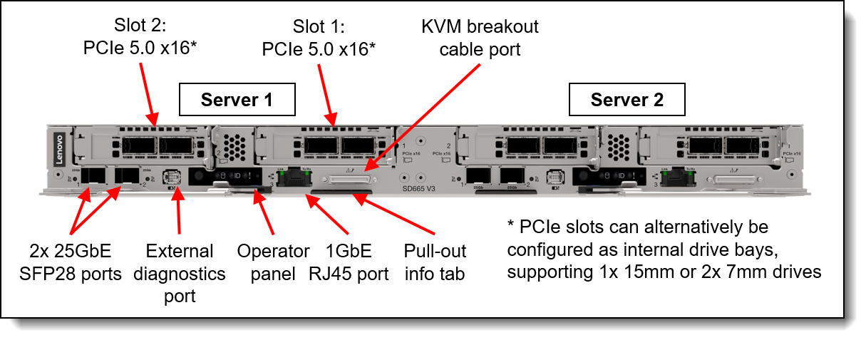
Figure 25. ThinkSystem SD665 V3 dual-server tray – front view
The selection of an optimized CPU for CAE workloads and corresponding memory depends on different parameters. For example, license cost for CAE software is often based on core count. This may drive a decision towards lower core count CPUs, resulting in a higher memory bandwidth per core. On the other hand, large models with strong scaling may benefit from higher core count CPUs.
For the general CAE use case on AMD CPUs, Lenovo recommends two AMD 9555 (48 cores, 300W) and 768GB of memory. For strong scaling models, alternatives are the AMD 9555 (64 cores, 400W) or AMD 9655 (96 cores, 400W).
For this Reference Architecture, we selected two AMD 9555 64 Core CPUs per node, which provide a large number of Zen5 Cores, optimized for strong scaling models. The high core count number is matched by 24 * 64GB 6400 MHz RDIMMs per Compute Node for 1.5 TB of memory capacity and high bandwidth. The actual CPU selection for a specific project should be based on the individual requirements – half the memory size and a AMD 9555 CPU may also be a good choice if there is more focus on the software license cost.
More details on the SD665 V3 and DW612S enclosure can be found in the product guide:
https://lenovopress.lenovo.com/lp1612-lenovo-thinksystem-sd665-v3-server
Bill of Materials (BOM) for AMD server-based scale-out SU
The following Bill of Materials (BOM) include only the significant parts of the Scalable Unit (SU) building bloc – other parts like Risers or Power supplies have been removed for better readability. The Lenovo sales configurators DCSC and x-config will help to create a valid configuration from the following BOM lists.
In addition to the Compute Node SUs as described in this BOM, there are central components that need to be provided, for example
- Omni-Path leaf switches (for management/login/storage) and spine switches
- Ethernet leaf switches (for management/login/storage) and core switches
- Management, login and storage systems
Also adjust the SU BOM to your specific situation as needed (e.g. cable lengths from the SU to spine/core switches are 30m in this BOM – shorter or longer cable lengths may be required for connecting to the central spine/core switches are needed, depending on the location of the racks in the data center). Also, the CPU and memory selection should be adjusted to the individual requirements as needed (for guidance, see the comments in the previous section).
Summary
This document has presented a comprehensive set of Lenovo Reference Architectures designed to meet the evolving computational demands of modern Computer‑Aided Engineering (CAE) workloads. As CFD and FEA simulations continue to grow in complexity, resolution, and operational scale, the need for highly optimized High‑Performance Computing (HPC) infrastructures has become a foundational requirement for engineering‑driven organizations. The Reference Architectures outlined in this paper address these requirements through carefully validated system designs that combine advanced CPU technologies, high‑bandwidth memory subsystems, and the ultra‑low‑latency Cornelis CN5000 Omni‑Path High Performance Fabric.
Performance analyses demonstrate the substantial benefits realized through the integration of technologies such as MRDIMM memory - which provides significant bandwidth scaling - and the CN5000 fabric, which delivers the message rate, latency characteristics, and congestion‑management capabilities essential for strong scaling of tightly coupled CAE applications. These advancements translate directly into increased simulation throughput, improved solver efficiency, and the ability to explore higher‑fidelity engineering models within practical development timeframes.
For Entry Clusters, the proposed configurations offer cost‑optimized, modular HPC clusters built on Lenovo ThinkSystem air‑cooled rack servers, including Intel‑ and AMD‑based options. These designs emphasize reliability, ease of deployment, and operational simplicity, while ensuring that performance, scalability, and user experience remain aligned with the needs of smaller engineering teams.
For large‑scale, highly parallel HPC environments, the Lenovo Neptune‑based liquid‑cooled platforms - SC750 V4 for Intel and SD665 V3 for AMD - provide industry‑leading density, sustained CPU frequency, and superior energy efficiency. When combined with CN5000 Fat‑Tree network topologies, these Scalable Units deliver predictable performance from rack‑level installations to multi‑rack CAE supercomputing environments capable of supporting thousands of compute nodes.
Across all configurations, Lenovo EveryScale principles ensure consistent interoperability, streamlined deployment, validated hardware/firmware recipes, and reduced integration risk. This holistic approach enables customers to accelerate HPC adoption and confidently deploy systems tailored to their workload characteristics, operational constraints, and long‑term scalability objectives.
In summary, the Lenovo CAE Reference Architectures provide a robust, forward‑looking foundation for organizations seeking to enhance simulation capability, reduce time‑to‑insight, and support engineering innovation at any scale. Through a combination of architectural rigor, technology leadership, and operational best practices, these solutions empower customers to deploy HPC environments that are optimized for performance, efficiency, and future growth.
Appendix - Cornelis CN5000 Omni-Path Fabric
The following table provides a full list of the Lenovo part numbers and feature codes for ordering the Cornelis CN5000 Omni-Path Fabric components.
Authors
Karsten Kutzer is Principal HPC/AI Solution Architect in the HPC Solutions and Server strategy department at Lenovo. He has a history of 25 years working in HPC, starting with deploying HPC clusters, then moving on to a role as an HPC architect. Since 2015 he has worked as HPC solution architect in Lenovo. His experience covers a wide range of topics from large-scale HPC clusters, servers, networking, storage and software stack as well as datacenter infrastructure and direct-water-cooling. He holds a degree of “Diplom Ingenieur (Technische Informatik)” from the Berufsakademie Mannheim.
Kevin Dean is the Senior Manager of the HPC/AI Solution Architect Team in the ISG Offerings Group at Lenovo. Kevin oversees the strategy and processes for HPC and AI solutions in this position, contributes his knowledge of HPC/AI application performance, and serves as the CAE/manufacturing architect. Kevin has over 20 years’ experience in HPC, AI, and computational engineering, including nine years at Lenovo focused on HPC/AI performance and solution architecture, and 12 years in aerodynamic design and CFD for the U.S. defense and automotive racing sectors. He earned his Master’s Degree in Aerospace Engineering at the University of Florida, following a Bachelor’s in the same field from Virginia Polytechnic Institute and State University.
Special thanks to Gilad Berman, David Decastro, Martin Hiegl, and the Cornelis Networks team for providing input and feedback to this paper.
Trademarks
Lenovo and the Lenovo logo are trademarks or registered trademarks of Lenovo in the United States, other countries, or both. A current list of Lenovo trademarks is available on the Web at https://www.lenovo.com/us/en/legal/copytrade/.
The following terms are trademarks of Lenovo in the United States, other countries, or both:
Lenovo®
from Exascale to Everyscale®
Neptune®
ThinkSystem®
XClarity®
The following terms are trademarks of other companies:
AMD and AMD EPYC™ are trademarks of Advanced Micro Devices, Inc.
Intel®, the Intel logo and Xeon® are trademarks of Intel Corporation or its subsidiaries.
Linux® is the trademark of Linus Torvalds in the U.S. and other countries.
Dynamics and Fluid are trademarks of Microsoft Corporation in the United States, other countries, or both.
IBM® is a trademark of IBM in the United States, other countries, or both.
NVIDIA® is a trademark of NVIDIA Corporation.
Other company, product, or service names may be trademarks or service marks of others.
Configure and Buy
Please select a locale
Full Change History
Course Detail
Employees Only Content
The content in this document with a is only visible to employees who are logged in. Logon using your Lenovo ITcode and password via Lenovo single-signon (SSO).
The author of the document has determined that this content is classified as Lenovo Internal and should not be normally be made available to people who are not employees or contractors. This includes partners, customers, and competitors. The reasons may vary and you should reach out to the authors of the document for clarification, if needed. Be cautious about sharing this content with others as it may contain sensitive information.
Any visitor to the Lenovo Press web site who is not logged on will not be able to see this employee-only content. This content is excluded from search engine indexes and will not appear in any search results.
For all users, including logged-in employees, this employee-only content does not appear in the PDF version of this document.
This functionality is cookie based. The web site will normally remember your login state between browser sessions, however, if you clear cookies at the end of a session or work in an Incognito/Private browser window, then you will need to log in each time.
If you have any questions about this feature of the Lenovo Press web, please email David Watts at dwatts@lenovo.com.


